Articles and Press Releases

Robert Berry

Recent Posts by Robert Berry:

2-D construction technique to create an isometric view

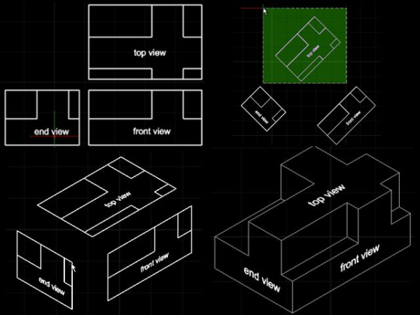
The following IntelliCAD end-user tip and trick is a 2-D construction technique that manipulates the top, front and end views with a series of rotations and non-uniform scaling factors so that the resulting geometry can be combined to give the appearance of a 3-D isometric drawing.

combo iso image resized 600

  • You start with the 2-D drawings of each of the top, front and end views.
  • You rotate the top view in a counterclockwise direction of +45°.
  • You repeat a similar rotation of +45° for the front view.
  • The end view is however rotated in a clockwise direction of -45°.
  • You then turn each of the views into a block by using the block command. Give each block a name corresponding to its view.

  • Then insert the top view block with a Y scaling of 0.57735. Be sure to leave the X and Z scaling at one. Also ensure rotation is 0°.
  • Then insert the front view block. This time the X scaling should be 0.57735 with the Y and Z scaling at one. Rotation for this block should be -30°. Place this block in the drawing below and to the right of the top view block.
  • Insert the end view block. This also has an X scaling of 0.57735 with the Y and Z scaling at one, but the rotation is in a +30° direction. Insert this to the left and below the top view.
  • The blocks can now be snapped together and exploded to allow familiar 2-D modification techniques to trim and add lines as needed to give the desired 3-D isometric appearance.

If you are interested in purchasing IntelliCAD you can locate an appropriate IntelliCAD technology consortium member via the following website members.IntelliCAD.org/members.

If you're interested in becoming a member of the consortium please contact us via twitter @IntelliCAD or via email ITCsales@IntelliCAD.org

Topics: IntelliCAD DWG Isometric 2-D construction technique top view front view end view

Creating Custom Objects in IntelliCAD

One of the most powerful features of the IntelliCAD development platform is the ability to create custom entities (also known as custom objects). Developers can define the behavior of custom entities which can greatly improve the user’s experience, enhancing productivity.

How can custom entities improve your user’s CAD experience? Let’s use the example of drawing a floor plan to explain. When drafting a floor plan using primitives (lines, arcs, circles) a user will combine these primitives to make a door shape or block that can be used throughout the drawing. If a new door size is required then the shapes have to be redrawn from scratch. Lines are used to draw walls and must be manually trimmed; if a wall’s angle is changed all the door shapes have to be manually realigned with the wall lines.

However, an application developer can define custom entities for walls, doors and windows. Since you define the behavior of these entity types you can define their name, how they are inserted, how they scale, are mirrored, their properties and how they interact with other entities — either primitives or additional custom entities. You can create the door object with properties such as width and height (common terminology for doors), and define the behavior of how doors will work when those properties change and how they relate to the environment.

For example, doors need to be not only inserted into a wall but also need to create break lines on the wall itself. Then when the door is moved, the wall needs to rebuild and create a new hole in the new position. The custom door entity can be defined to allow the swing to flip, not to mention changing the width or height of the door itself. When the door is copied and pasted does it stick within the wall or is a freestanding door allowed within the drawing? Is it possible to allow regular CAD editing commands (move, copy, trim, extend, stretch) to interact with the custom door entity? Also the developer can define what the custom entity will look like in different views: 2D plan, elevation and 3D view.

What is important to note here is that custom objects allow the programmer to not only define the appearance, properties and associated data of the object but also to define its behavior in relation to its environment and likewise the environment in relation to the object. This ability to create behavior and use terminology that is familiar to the target user greatly improves user productivity. The complexity of a custom object really is up to the programmer but they should consider:
• How the entity is saved in the .dwg file
• How the graphics and geometry are displayed in both the viewports and 2D/3D world environments
• The names of properties and the behavior when those properties change
• How the entity works with various snap modes
• How many grip points will be available and how they behave
• How the entity intersects with the other entities in the drawing
• What happens when the entity is exploded or viewed in other programs
• What relationships the entity may have with other entities in the drawing
• How the entity displays and behaves when your application is not present

Developers define the behavior of their custom entities in application extension DLLs, but you can also define some basic behavior for your entities when your application DLL is not present. Developers can define proxy graphics and determine if some basic editing (like copy or move) can be done without their application. However, in the case of a door entity it would be impossible for it to resize properly when the properties where changed or to automatically update walls if the underlying application was missing. The proxy functionality only allows your .dwg files that contain custom entities to have some basic behavior when loaded in other CAD applications. Then again, if you choose to force the user to purchase your application you can disable all proxy functionality so the custom entities are useless without your underlying application.

To get the full behavior of a custom entity, the underlying application DLL needs to be loaded within IntelliCAD prior to opening a drawing that contains custom entities. This can be done either manually [via the APPLOAD command] or automatically when the IntelliCAD program starts [by dropping the IRX file into the IntelliCAD program folder].

The IntelliCAD API provides a simple sample application that demonstrates the power of custom entities. The API installation files are usually shipped with the IntelliCAD program but can also be found on the IntelliCAD beta forum. The following movie shows how to load, install, and experiment with the sample custom entity application included within the IntelliCAD API:

The sample discussed here is included in the API samples and documentation. Although the source code is available to build the application from scratch, the IRX DLL release version is also prebuilt and waiting for you to load it.

If you are a developer interested in using the IntelliCAD platform please contact Robert Berry via Skype at Robert.Berry.ITC and apply for access to our beta forum so that you can test the software for yourself.

Topics: IntelliCAD DWG IntelliCAD® 7 CAD programming BIM ARX IRX custom objects custom entities

Programming with IntelliCAD

The IntelliCAD Technology Consortium (ITC) is a nonprofit organization that delivers a safe and affordable CAD programming platform for its members. Each of the consortium’s commercial members share the source code of the IntelliCAD program and invariably add their own specialty solutions for their own niche markets.

At its core, the IntelliCAD program is based on and expands the Open Design Alliance (ODA) programming interface (API) called Teigha. The ODA is also a nonprofit organization that supplies .dwg programming libraries to its members. The IntelliCAD IRX API can be considered an extension of the Teigha API.

Traditionally, a recipe for success when creating a compiler for programming purposes is to use the programming language of the compiler to write additional functionality within the compiler itself. This methodology ensures that the programming language is sound in that it has to be used in order to create itself, layer upon layer. In a similar way the IntelliCAD program is written using the ODA Teigha libraries. The entire IntelliCAD source code is in fact a set of examples showing how to use the Teigha/IRX interface to create CAD programming solutions.

Resultantly, the preferred method of programming within IntelliCAD is by using the IRX API. Although several other APIs are available, IRX, an object oriented C++ API is our most powerful API with the ability to create custom objects and provides the best performance for complex solutions.

There are however a multitude of different programming APIs that are available to developers who are interested in using the IntelliCAD platform.

At an end-user level, there is the ability to record and save macros in a text format. These text files can later be edited, loaded and run as a script, thereby saving the user a great deal of time on repetitive tasks. This text script format effectively gives access to all of the commands that can be typed into the IntelliCAD command line.

The IntelliCAD menu structure is also based on a TXT format which enables full customization of the menu either from within or outside the program. Developers can easily replace or add to the existing IntelliCAD menu structures. Other menu programming tools such as DCL and DIESEL are also supported.

At the next level, IntelliCAD offers a LISP programming interface that is extremely similar to AutoCAD’s AutoLISP. If you create LISP commands from within IntelliCAD, they can be run in AutoCAD. The LISP interpreter is an internal API and can even be combined with the macro recording language mentioned above.

IntelliCAD also includes the Solutions Development System (SDS), which is a C/C++ language interface comparable with the ADS® (AutoCAD® Development System). The SDS system is more like C versus C++ in that it does not have the ability to create custom objects but it can support complex solutions development. IntelliCAD is compatible with ADS programs and several ITC members have successfully imported millions of lines of ADS code to IntelliCAD.

IntelliCAD also supports many different flavors of COM programming. Direct COM development can be done in C/C++. We also support the Visual Basic for Applications interpreted compiler within the IntelliCAD program and the Visual Basic development environment for compiling outside of IntelliCAD. You can even do C# development from within IntelliCAD and support for this API is improving all the time.

If you are interested in finding out if IntelliCAD can solve your CAD development needs, please contact me, Robert Berry via Skype at Robert.Berry.ITC.

Join the IntelliCAD Technology Consortium

Topics: DWG CAD Platform CAD programming ITC ADS ARX IRX AutoLISP Lisp

Creating BIM applications on top of IntelliCAD

The concept of BIM technology has been around since the 1960s. Over the past 20 years 3-D modeling has been actively used in the automotive and aviation industries to model cars, ships and airplanes. However it has been only relatively recently that the AEC building industry has been "revolutionized" by information modeling technology.

Previously, architects and engineers used CAD as an electronic drafting board to create their plans, but these drawings were essentially "non-intelligent" containing only the geometry of lines, arcs and text. Over the past several years there have been many new software offerings that have attempted to change the fundamental methodology of how architectural drawings are created by trying to build intelligence into a model which is then used to generate construction documents. Some of this software is intriguing but actually many architects and engineers still need, and often prefer, the traditional 2D lines and arcs to complete certain custom areas of the drawing.

CAD Projekt is a leading Interior Design company based in Poland that delivers a joint solution in their IntelliCAD offering. Their users experience the best of both worlds in that they can use all of the traditional 2D and 3D CAD tools but still benefit from integrated BIM technology that can be imported via the IFC file format.

CAD Projekt chose IntelliCAD over other CAD platforms its open source, reliability, familiar user-friendly interface and its full compatibility with the .dwg file format. As a Commercial member of the ITC, CAD Projekt has unlimited distribution rights for an extremely low royalty rate, allowing them to supply their worldwide customer base with the full IntelliCAD program alongside their own software at no additional charge. Furthermore, access to the IntelliCAD source code accelerates development and allows them to tightly integrate their own software to ensure better performance and reliability.

CAD Projekt says their success would have been impossible to achieve without their partnership with the ITC. They say the knowledge and experience of the ITC’s international development team ensures the highest quality solutions and allows them to direct all their efforts towards their own vertical applications.

“Becoming a part of ITC was not only a great economical and programming solution, but also an important turn in our understanding of globalization. We feel that together we can create much better solutions to serve our customers,” says Mr. Adam Sterczala, Economical Director and co-founder of CAD Projekt K&A.

If you are interested in using IntelliCAD as your CAD development platform then please contact me via Skype at Robert.Berry.ITC and I will do my best to work with you to establish if IntelliCAD does in fact meet your development requirements.

This movie gives a presentation specifically about the CAD Decor Pro product...

Topics: IntelliCAD DWG BIM ITC Architecture

AutoCAD IntelliCAD share 396 commands & 507 system variables!

The old adage that most people only use a fraction of the features contained in a computer software program is applicable when comparing the features of AutoCAD® versus IntelliCAD.

IntelliCAD shares over 396 of the most important commands in AutoCAD as well as over 507 system variables. This means that the vast majority of CAD users will have more functionality than they will ever need when using the IntelliCAD program.

A full list of the features shared by both programs can be found in the link below.

IntelliCAD v7 shares important features with AutoCAD.pdf

Topics: DWG IntelliCAD® 7 Product Information